
Basic (B) Servo Worm Reducers
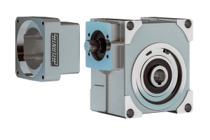
This standard range of Servo-Worm Reducers are perfect for use in applications that demand good performance, positioning and repeatability. They were specifically developed for use with state-of-the-art servo motor technology, providing tight integration of the motor to the unit. Angular backlash of less than 12 arc-minutes is provided standard.
They are available in two sizes (50 mm and 63 mm center distance) with input speeds up to 5,000 rpm, reduction ratios from 4.75 to 52:1 and output torque capacities up to 126 lb.ft. A wide range of motor couplings and mounting flanges are available for assembly to virtually all servo motors, and the hollow bore output can be used to mount output shafts, pinion shafts, or other drive elements.
Typical applications for these reducers include precision rotary axis drives, traveling gantries & columns, material handling axis drives and electronic line shafting. Industries served include Material Handling, Automation, Aerospace, Machine Tool and Robotics.
- Unit Design &
Construction - Unit Selection
- Unit Ratings
Gearing: Internal gear design was optimized to provide an angular backlash of less than 12 arc-minutes.
Bearings: Input angular contact bearings for high input speed, and ball bearings for good radial and axial load capacity.
Housing: Light weight aluminum housing for good heat dissipation, with integral input flange for servo motors and universal mounting on any face.
Output: The output bore is available with a keyway or a compression-type hub (see dimension pages). We offer a line of accessories to adapt this output to straight shafting, Rack & Pinions, or other gearing types.
These reducers are typically selected based on the peak cycle forces, which usually happen during accelerations and decelerations. These cycle forces depend on the driven load, the speed vs. time profile for the cycle, and any other external forces acting on the axis. For more selection information, please follow this PDF link.
For application & selection assistance, please call, fax or email us. Your application information will be reviewed by our engineers, who will recommend the best solution for your application.
The following table gives the output torque ratings (in lb.ft.) for the Basic (B) Servo Worm Reducers at various input speeds and ratios. Service factors need to be applied to these ratings to make a proper selection.
To see the unit dimensions of each size, click the "Unit Size" in the left column.
| Unit Size (C.D.**) |
Gear Ratio | Peak Torque (lb.ft.)* |
Output Torque (lb.ft.) based on Input Speed* | |||||
|---|---|---|---|---|---|---|---|---|
| 500 rpm | 1,000 rpm | 1,500 rpm | 3,000 rpm | 4,000 rpm | 5,000 rpm | |||
| 3 (50 mm) |
4.75 | 365 | 40 | 46 | 46 | 46 | 43 | 41 |
| 6.75 | 266 | 36 | 42 | 46 | 46 | 43 | 41 | |
| 9.25 | 180 | 31 | 36 | 39 | 46 | 46 | 43 | |
| 14.50 | 234 | 37 | 43 | 46 | 50 | 50 | 50 | |
| 19.50 | 162 | 29 | 33 | 37 | 43 | 43 | 43 | |
| 29.00 | 198 | 32 | 37 | 40 | 46 | 46 | 43 | |
| 39.00 | 135 | 35 | 40 | 43 | 50 | 50 | 50 | |
| 50.00 | 99 | 28 | 31 | 33 | 40 | 40 | 40 | |
| 4 (63 mm) | 4.75 | 666 | 106 | 120 | 113 | 96 | 90 | |
| 6.75 | 495 | 106 | 120 | 113 | 96 | 90 | ||
| 9.25 | 333 | 77 | 86 | 90 | 90 | 90 | ||
| 14.50 | 396 | 103 | 120 | 120 | 113 | 106 | ||
| 19.50 | 333 | 77 | 86 | 90 | 110 | 103 | ||
| 29.00 | 432 | 116 | 136 | 146 | 130 | 123 | ||
| 39.00 | 297 | 90 | 106 | 116 | 126 | 126 | ||
| 52.00 | 198 | 63 | 77 | 83 | 100 | 106 | ||
*Ratings are based on servo operation and 12,000 hours running at rated torque. For continuous operation, please consult the factory. Peak torque values are based on the ultimate strength of the gearing. Information is subject to change without notice.
**C.D. = Center Distance of reducer, which is the vertical distance from the input shaft to the output shaft.