
Choosing The Right Rack & Pinion
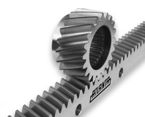 Rack and pinions are one of the oldest and simplest mechanisms used for converting rotary motion into linear motion. They are extremely versatile and can be used in a wide range of applications, from simple, hand operated machinery to highly dynamic, ultra-precise machine tool applications.
In recent years there have been huge advancements in the design and manufacturing of rack & pinion drives. By varying the rack & pinion tooth size, hardness, quality level and style, a wide range of solutions are now available to choose from.
This wide range of solutions has made selecting the right rack & pinion drive a daunting task for the machine designer. The goal of this whitepaper is to review the wide range of rack & pinion drives available and look at the main considerations when selecting a rack and pinion drive so the best solution can be found to meet the machine requirements.
Manufacturing of Rack & Pinions
To understand the wide variety of rack & pinion drive solutions available, it is important to understand the manufacturing processes used to create them and what benefits they provide. The manufacturing processes used, as well as the tooth size (module) and raw material used, will dictate the force capacity and quality of the gearing.
What is a Module?
The “module” of a rack & pinion denotes the size and pitch of the gear teeth. A smaller module means a smaller tooth and a larger module means a larger tooth. Sizes can be as low as module 1.0 up to module 16 in special cases. The tooth height of a rack is denoted as 2.25 times the module, so a module 1.0 would be a tooth height of 2.25 mm and a module 10.0 would have a tooth height of 22.5 mm. The pitch of a rack is denoted by the module times pi, so a module 1.0 would have a pitch of 3.14 mm and a module 10.0 would have a pitch of 31.41 mm.
The pitch diameter of a pinion is denoted as the module times the number of teeth, so a 20-tooth module 1.0 would have a pitch diameter of 20.0 mm and a 20-tooth module 10.0 would have a pitch diameter of 200.0 mm.
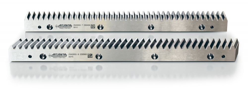
Milled Racks (Soft, Quenched & Tempered)
These racks have milled teeth and are the simplest and most economical type available but have low force capacities due to their soft or quenched & tempered teeth. Their tooth quality is typically average (DIN 8 – 9, AGMA 9 – 10), with a pitch deviation (the linear error from tooth-to-tooth) range of +/- 0.100 mm to +/- 0.150 mm per meter. This makes milled racks ideal for lighter, smaller machines with average speed and accuracy requirements.
Induction-Hardened Racks
To increase the force capacity of milled racks, the teeth can be induction hardened. This dramatically increases the force capacity of the rack but conversely reduces the tooth quality due to deformation from the hardening process. Their tooth quality is low (DIN 10, AGMA 8), with a pitch deviation of +/- 0.200 mm per meter. This makes induction-hardened racks ideal for heavy, large machines with low speed and accuracy requirements.
Hardened & Ground Racks
To have the high force capacity of the induction-hardened racks but with better tooth quality, the teeth can be ground. Extra material is left during the milling of the teeth so they can be ground after hardening, which dramatically increases the quality of the teeth. Their tooth quality is high (DIN 5 – 7, AGMA 11 – 13), with a pitch deviation range of +/- 0.034 mm to +/- 0.060 mm per meter. This makes hardened & ground racks ideal for high force and accuracy machines with high dynamic requirements.
The following table shows rack force ratings based on the module size and rack type:
| Rack & Pinion Size |
Tangential Force Ratings | |||
|---|---|---|---|---|
| Hardened & Ground Rack |
Induction-Hardened Rack |
Quenched & Tempered Rack |
Soft Rack | |
| Module 1.5 | 1,600 lb. | 780 lb. | --- | 200 lb. |
| Module 2.0 | 4,100 lb. | 2,000 lb. | 1,100 lb. | 560 lb. |
| Module 3.0 | 6,700 lb. | 3,400 lb. | 1,900 lb. | 900 lb. |
| Module 4.0 | 13,000 lb. | 6,700 lb. | 3,600 lb. | 1,800 lb. |
| Module 5.0 | 16,000 lb. | 10,000 lb. | --- | 2,900 lb. |
| Module 6.0 | 24,000 lb. | 15,000 lb. | --- | 4,200 lb. |
| Module 8.0 | 42,000 lb. | 26,000 lb. | --- | 7,600 lb. |
| Module 10.0 | 64,000 lb. | 40,000 lb. | --- | 12,000 lb |
| Module 12.0 | 92,000 lb. | 56,000 lb. | --- | --- |
Pinion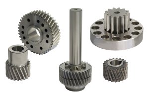 s also come in a variety of manufacturing types, including soft, induction-hardened and hardened & ground. Soft pinions have soft, milled teeth and are typically used in light, low accuracy and less demanding applications and are an economical choice. To increase the load capacity of soft pinions, the teeth can be induction-hardened but the quality level is reduced due to the hardening process.
Since the pinion sees the most cycles, the hardness and quality level of the pinion teeth should always be equal to or greater than that of the rack teeth. For most applications, hardened & ground pinions offer the best solution, with high accuracy and force capacity with smooth operation and versatility of mounting.
Selecting The Right Rack & Pinion Drive
When selecting a rack and pinion drive, it is important to gather as much information as possible about the specific application so the maximum forces, speed, accuracy and lifetime can be determined.
Forces:
The typical forces on a rack and pinion drive are from:
- Acceleration and deceleration forces to move a mass (F = ma)
- Friction from the type of linear supports used (linear rails, rollers, ways, etc.)
- Additional process forces such as cutting, welding and clamping forces.
The full duty cycle should be evaluated to determine when the peak cycle forces occur. In most applications, the peak cycle forces happen during acceleration so the sum of the above forces is typically used.
Accuracy:
The accuracy of a rack and pinion drive is usually defined by the required positioning accuracy and repeatability. Positioning accuracy is dictated by the cumulative pitch deviation of the gear rack, which is the linear error from tooth to tooth and is a function of the manufacturing processes used (see above).
For example, a gear rack with a pitch deviation of +/- 0.200 mm over 1,000 mm would mean the actual rack length would deviate between 999.8 and 1000.2 mm compared to the theoretical length of 1,000 mm.
This linear error can be minimized by using high quality gearing or by mapping the errors to minimize the cumulative error. In some cases, it is possible to compensate for the error and completely eliminate it for full length of the axis.
The repeatability of a rack and pinion drive is directly related to the backlash (or linear play) at the gear mesh. When motion is stopped or reversed, the backlash can result in lost motion between the pinion and rack, which would cause positioning errors. However, backlash is important to prevent binding at the gear mesh and to leave room for lubrication. Backlash can be minimized by using high quality gearing and accurate mounting. It is also possible to completely eliminate the backlash by using split-pinions or dual pinion drives.
The following table shows rack quality levels and accuracy, as well as typical applications, based on the rack type:
| Rack Class: | Rack Type: | Tooth Quality: |
Pitch Accuracy: |
Typical Applications: |
Helical: |
Straight: |
|---|---|---|---|---|---|---|
| Basic (BR) |
Induction Hardened |
DIN 10 (~AGMA 8) |
< 0.200 mm per meter |
Heavy Loads Low Accuracy |
39-Series | 27-Series 34-Series |
| Soft | DIN 9 (~AGMA 9) |
< 0.150 mm per meter |
Light Loads Medium Accuracy |
47-Series | 25-Series 36-Series (Stainless) |
|
| Precision (PR) |
Quenched & Tempered |
DIN 8 (~AGMA 10) |
< 0.100 mm per meter |
Medium Loads Medium Accuracy |
38-Series | 33-Series |
|
Hardened & Ground |
DIN 8 (~AGMA 10) |
< 0.060 mm per meter |
Heavy Loads High Accuracy |
29-Series | 28-Series | |
| High Precision (HPR) |
Hardened
& Ground |
DIN 7 (~AGMA 11) |
< 0.052 mm per meter |
Heavy
Loads High Accuracy |
29-Series | 28-Series |
| DIN 6 (~AGMA 12) |
< 0.036 mm per meter |
29-Series | 28-Series | |||
| Ultra-High Precision (UHPR) |
Hardened & Ground |
DIN 5 | < 0.026 mm per meter |
Heavy
Loads Ultra-High Accuracy |
29-Series | 28-Series |
| DIN 3 | < 0.012 mm per meter |
48-Series | 46-Series |
Speed:
The maximum linear speed of an axis is important for calculating acceleration but also for determining the best style of rack and pinion to be used. When linear speeds are high (over 2 m/s), the noise generated from the gear mesh can become a problem.
Helical gearing, which has its teeth at an angle to the rack length (typically 19º 31' 42" helix angle), can provide quiet and smooth operation with increased load capacity compared to spur gearing due its larger contact area. Helical racks can also have nice round numbers for length (e.g. 500.00 mm and 1,000.00 mm) compared to straight racks that have lengths that are a multiple of pi (e.g. 502.65 mm and 1,005.31 mm). For these reasons, helical gearing makes the best solution for high speed axis drives. The only drawback to using helical gearing is that the helix angle will produce a side (axial) force that is a function of the tangential drive force.
Design Considerations
When designing an axis drive using a rack & pinions, there are some design considerations that should be closely looked at, such as lubrication, environment, mounting and alignment.
Lubrication:
The lifetime of a rack and pinion drive is an important consideration, especially with high duty cycle applications. When properly selected, a rack and pinion drive can have a near infinite life, assuming it has adequate lubrication and proper mounting.
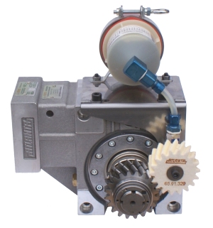
Lubrication is critical to prevent metal-to-metal contact on the rack & pinion tooth flanks. Without an adequate film of lubrication at the gear mesh, normal wear and tear can be accelerated, which can affect the performance of the axis and reduce the lifetime of gearing. On a rack and pinion drive, lubrication can be done manually or through an automatic system. An automatic lubrication system is preferable for its precise dosing of lubricant and its low maintenance. Automatic lubricators can pump grease directly to a brush or felt gear for precise application of lubricant, providing continuous lubrication of the gearing.
In cases where lubrication of the gearing is not possible, such as in dirty or washdown environments, it is possible to run dry (without lubrication) but the gearing must be oversized to compensate for the increased wear and tear but the operating lifetime cannot be guaranteed.
Environment:
The environment that the rack & pinion drive is going to be used is important to take into account. If it is a dirty environment with debris in the area of the drive, the rack & pinion should be oriented with teeth facing down, or shielded to prevent contamination of the gearing.
If the drive is going to be used in a wet or corrosive environment, the rack & pinion may need to be coated to protect them. Stainless steel rack & pinions are also an option for such an environment.
Mounting & Alignment:
When designing a rack and pinion axis drive, it is important to ensure that the gearing can be properly aligned during assembly. The design should allow adjustment of the backlash, as well as the perpendicularity and parallelism of the gearset. This will ensure there is proper contact at the gear mesh with no binding, while providing room for lubrication.
A small amount of backlash should always be present at the rack & pinion gear mesh. High quality, hardened and ground gearing can accept a minimum backlash of 0.02 mm (0.0008”) while low quality induction hardened gearing can accept a minimum backlash of 0.08 mm (0.032”). The backlash level should be set at the high point of the racks pitchline, which will set the minimum backlash value and prevent any binding along the entire rack travel length.
The contact pattern of the gearset should be checked by marking or “bluing” the pinion teeth with a high spot paste and slowly running the axis in both directions. This will show the contact pattern at the gear mesh and show any misalignment. The ideal contact pattern would be centered on the pitchline and extending across the face width of the gearing.
Selection Examples
Budget CNC:
A manufacturer of CNC machinery is looking to build a budget friendly 8’ x 12’ CNC router for woodworking. Accuracy and force requirements are relatively low.
In this case, a helical module 1.5 or module 2 soft, milled rack and hardened & ground pinion would be a great fit. The soft rack offers a good balance of force capacity, precision and cost. Since this type of machine usually has low cycle forces, there is no need for use a hardened rack. Soft or hardened & ground pinions could be used and would mount to a gearbox output shaft or a hollow bore right angle reducer.
Heavy Vertical Lift:
An OEM of material handling equipment wants to build a vertical lift capable of handling 5,000 lbs. Accuracy and speed are not critical for this and can be kept low.
For this application, an induction-hardened straight rack and hardened & ground pinion would be a great fit. Since accuracy and speed are low, a low quality induction-hardened rack will be more than adequate. Straight tooth gearing is more than capable to handle the loads and speeds and will not have the side force associated with helical gearing.
High Speed Robotic Transfer Unit:
A machine builder wants to build a highly dynamic and accurate 7th axis robotic transfer unit (RTU). The maximum linear speed is up to 4 m/s with precise positioning and repeatability required. At these demanding speeds, helical hardened & ground gearing would be perfect to handle the high dynamic moves being made with high positioning accuracy, while offering quiet and smooth operation.
Conclusion
 When selecting a rack and pinion drive for an application, it is important to consider all of the applications parameters to determine the forces, speeds and accuracy required. Once these are defined, it is possible to select the best rack and pinion drive solution to meet the application requirements.
Furthermore, it is important to take into consideration the mounting, alignment and lubrication requirements that come with designing a rack and pinion system.
For more information, contact ATLANTA Drive Systems at: (800) 505-1715, or on the web at: www.atlantadrives.com.