Related Resources
StrongLine Gear Racks Operating Manual PDF Catalog Files Automatic Lubrication Systems Application Sheets Frequently Asked QuestionsOther Products Available
High-Precision Hardened & Ground Racks
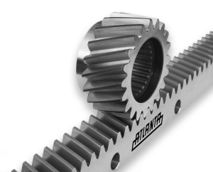
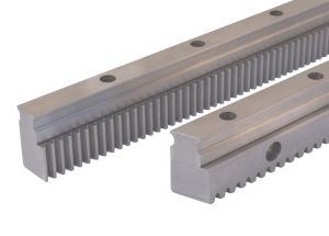
ATLANTA has expanded their wide range of racks to include Ultra-High Precision DIN 3 and 5 racks, which are precision manufactured in a controlled environment.
Four levels of precision are now available (DIN 3 through 7, AGMA 11 to 12+), with pitch accuracies down to 0.012 mm per 1,000 mm length. This gives the machine designer the flexibility of choosing the desired level of rack precision to meet the application needs.
These racks are available in straight (spur) and helical versions, in modules 1.5 through 12.0, in lengths up to two meter long. These racks are ideal for high accuracy applications requiring minimal pitch error over the complete travel length.
The high precision pitch of the racks can eliminate the need for electronic compensation and the high precision parallelism allows for drives with extremely low backlash without the need for preloading. Used with our Split-Pinions, ultra-precise zero-backlash axis drives can be achieved.
Advantages of Using Long Racks: Through continuous improvements in production techniques, ATLANTA has been able to reduce the total pitch error for the 1,000 mm long hardened & ground racks, while achieving significant reductions of the total pitch error of 1,500 mm and 2,000 mm long hardened & ground racks.
- Precision Rack Range
- Helical Racks
- Straight Racks
- Rack Assembly Kit
| Rack Class | Tooth Quality | Tooth Pitches | Pitch Deviation GTf per 1,000 mm length |
Lengths Available |
|---|---|---|---|---|
| High Precision (HPR) |
DIN 7 (~AGMA 11) |
Module 2.0 to 10.0 | < 0.052 mm | 1.0 & 2.0 Meters |
| DIN 6 (~AGMA 12) |
Module 1.5 to 12.0 | < 0.034 mm | 0.5 to 2.0 Meters | |
| Ultra-High Precision (UHPR) |
DIN 5 StrongLine |
Module 3.0 to 6.0 | < 0.026 mm | 1.0 Meter |
| DIN 3 | Module 5.0 to 12.0 | < 0.012 mm | 1.0 Meter |
The quality levels denote the accuracy of the teeth, which affects the positioning accuracy, backlash and noise level of the rack & pinion set.
| Rack Size | Rack Part Numbers (click on part number for data sheet) |
|||
|---|---|---|---|---|
| DIN 3 * |
DIN 5 StrongLine * |
DIN 6 |
DIN 7 |
|
| Module 1.5 | --- | --- | 29.15.105 | --- |
| Module 2.0 | --- | --- | 29.20.100 | 29.20.107 |
| Module 3.0 | --- | 29.35.100 | 29.30.100 | 29.30.107 |
| Module 4.0 | --- | 29.45.100 | 29.40.100 | 29.40.107 |
| Module 5.0 | 48.50.105 | 29.55.100 | 29.50.105 | 29.50.107 |
| Module 6.0 | 48.60.105 | 29.65.100 | 29.60.105 | 29.60.107 |
| Module 8.0 | 48.80.105 | --- | 29.80.105 | 29.80.107 |
| Module 10.0 | 48.10.105 | --- | 29.10.105 | 29.10.107 |
| Module 12.0 | 48.12.105 | --- | 29.12.105 | --- |
* Available upon request
| Rack Size | Rack Part Numbers (click on part number for data sheet) | |||
|---|---|---|---|---|
| DIN 3 * |
DIN 5 StrongLine * |
DIN 6 |
DIN 7 |
|
| Module 2.0 | --- | --- | 28.20.100 | 28.20.107 |
| Module 3.0 | --- | 28.35.100 | 28.30.100 | 28.30.107 |
| Module 4.0 | --- | 28.45.100 | 28.40.100 | 28.40.107 |
| Module 5.0 | 46.50.105 | 28.55.100 | 28.50.105 | 28.50.107 |
| Module 6.0 | 46.60.105 | 28.65.100 | 28.60.105 | 28.60.107 |
| Module 8.0 | 46.80.105 | --- | 28.80.105 | 28.80.107 |
| Module 10.0 | 46.10.105 | --- | 28.10.105 | --- |
| Module 12.0 | 46.12.105 | --- | 28.12.105 | --- |
* Available upon request
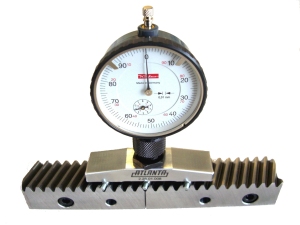
To set the pitch in-between rack segments, a companion rack is typically used. While this works well for most applications, it can induce error into the axis. This error can accumulate with each rack joint, especially on long axis drives.
When using our Precision Hardened & Ground Racks in high accuracy applications, we recommend using our Rack Assembly Kits to achieve the most accurate pitch in-between rack segments. The assembly kit consists of a measuring bridge, an adjusting device and magnetic rollers. With this kit, it is possible to achieve perfect rack joints without adding error to the system. A video showing how the Rack Assembly Kit is used can be found on our Videos page.
