Ultra-High Precision Rack & Pinion Drive Systems
For rack & pinion applications requiring ultra-precise positioning and repeatability, the system backlash can be eliminated by using two pinions - one to drive the axis and one to "preload" the axis to remove the backlash. Positioning accuracy is maintained during acceleration and deceleration, as well as during changes in direction of travel. We have several different different solutions to achieve a zero-backlash drive system:
 Split-Pinions
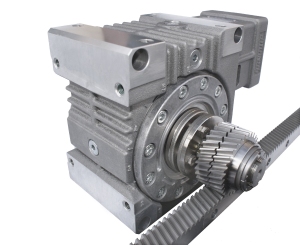
The simplest zero-backlash drive system utilizes a split-pinion, which consists of two pinion halves and an axial spring pack. The pinion halves mesh with opposite tooth flanks on the same rack, eliminating the backlash.
One pinion half drives the axis while the second pinion half is "preloaded" to remove the backlash. The preload setting of the second pinion half is fully adjustable on the machine by turning the axial spring pack at the end of the pinion shaft.
The split-pinion shafts mount directly into our High-Torque (HT) & High-Performance (HP) Servo-Worm Reducers.
 Dual-Pinion Electrical Preload
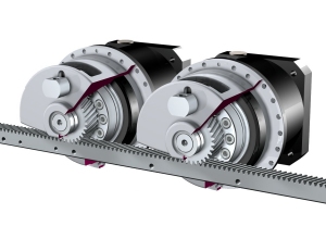
Another method to remove the backlash at the rack & pinion is to use two motor/reducer assemblies with dual pinions operating on the same rack in a master/slave setup.
One pinion drives the axis (the "master") while the second pinion is "preloaded" to remove the backlash (the "slave"). The preload is created electronically with a special motor controller; these systems can also be set up to drive together during cycle times when backlash is not critical.
Dual-pinion gearboxes using only one motor are also possible, please consult the factory.
Our Automatic Lubrication Systems are highly recommended for use with these drives, providing continuous grease lubrication to the rack & pinion tooth flanks to preserve the quality and lifetime of the gearing.
These drives are perfect for precise positioning applications, such as traveling gantries and columns, milling machines, CNC routers and material feel axis drives. Two reducers/motors can also be used to eliminate the axis backlash by electrical preload.
- System Precision
- Split-Pinion Rack &
Pinion Drive Systems - Electrical Preload Rack &
Pinion Drive Systems
The system precision, including the pitch error and backlash, can be found below:
| System Precision Level: |
Rack Type & Class: | Rack Quality Level: |
Rack Pitch Error: | Rack & Pinion Minimum Backlash:* |
|---|---|---|---|---|
| Ultra-High | Hardened & Ground (UHPR & HPR) |
DIN 3 to 6 (~AGMA 12+) |
< 0.012 to 0.036 mm per meter |
Zero |
*The rack and pinion backlash depends on the alignment of the rack to the linear guides.
There are three levels of precision for the hardened & ground racks, with rack pitch error ranging from 0.012 mm to 0.048 mm per meter length depending on which rack is used. Follow this link for more information on our Precision Racks.

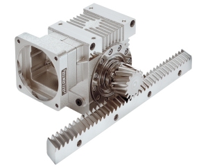
The simplest zero-backlash drive system utilizes a split-pinion, which consists of two pinion halves and an axial spring pack. The pinion halves mesh with opposite tooth flanks on the same rack, eliminating the backlash.
One pinion half drives the axis while the second pinion half is "preloaded" to remove the backlash. The preload setting of the second pinion half is fully adjustable on the machine by turning the axial spring pack at the end of the pinion shaft.
The split-pinion shafts mount directly into our Servo Reducers and are fixed in place by means of a compression coupling. This provides rigid support and tight integration of the split-pinion shaft into the reducer. The end result is a compact and ultra-precise positioning axis drive. These reducers have backlash levels down to one arc-minute and ratios from 4.75:1 to 52:1 (higher ratios available with planetary-worm reducers).
The maximum drive force that each system can handle (with safety factor 1.0) is listed below; this should be compared to the application peak force, which can be calculated here, or by filling out our Application Sheet.
Please click on values for PDF specifications:
| Reducer Size: |
Rack Module: |
Split-Pinion: |
Split-Pinion # of teeth: |
Maximum Drive Force:* |
Maximum Linear Speed: |
|---|---|---|---|---|---|
| HP Size 3 | 2 | 74.92.330 | 30 | 530 lb. | 8,288 in/min |
| 3 | 74.93.320 | 20 | 530 lb. | 8,288 in/min | |
| HT size 3 | 2 | 74.92.430 | 30 | 636 lb. | 8,288 in/min |
| 3 | 74.93.420 | 20 | 791 lb. | 8,288 in/min | |
| HP Size 4 | 2 | 74.92.430 | 30 | 636 lb. | 6,631 in/min |
| 3 | 74.93.420 | 20 | 1,124 lb. | 6,630 in/min | |
| HT Size 4 | 3 | 74.93.520 | 20 | 1,180 lb. | 6,631 in/min |
| 4 | 74.94.515 | 15 | 1,815 lb. | 6,631 in/min | |
| HP Size 5 | 3 | 74.93.520 | 20 | 1,180 lb. | 4,973 in/min |
| 4 | 74.94.515 | 15 | 1,815 lb. | 4,973 in/min | |
| HT Size 5 | 5 | 74.95.615 | 15 | 2,447 lb. | 6,216 in/min |
| 6 | 74.96.613 | 13 | 3,423 lb. | 6,465 in/min | |
| 8 | 74.98.612 | 12 | 2,781 lb. | 7,957 in/min | |
| HP Size 6 | 5 | 74.95.615 | 15 | 2,248 lb. | 6,216 in/min |
| 6 | 74.96.613 | 13 | 2,248 lb. | 6,465 in/min | |
| 8 | 74.98.612 | 12 | 2,248 lb. | 7,957 in/min | |
| HT Size 6 | 6 | 74.96.713 | 13 | 3,531 lb. | 6,465 in/min |
| 8 | 74.98.712 | 12 | 4,002 lb. | 7,957 in/min | |
| HP Size 7 | 6 | 74.96.713 | 13 | 3,531 lb. | 4,246 in/min |
| 8 | 74.98.712 | 12 | 4,721 lb. | 5,226 in/min |
* Force ratings do not include any safety factors. Drive forces vary depending on gearbox ratio selected.

Another method to remove the backlash at the rack & pinion is to use two motor/reducer assemblies with dual pinions operating on the same rack in a master/slave setup.
One pinion drives the axis (the "master") while the second pinion is "preloaded" to remove the backlash (the "slave"). The preload is created electronically with a special motor controller; these systems can also be set up to drive together during cycle times when backlash is not critical.
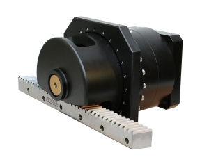
Our new HighForce Planetary Drives, which can handle highly dynamic and heavy loads, are perfect for these applications. These reducers have backlash levels down to one arc-minute and ratios from 4:1 to 100:1.
The maximum drive force that each system can handle (with safety factor 1.0) is listed below; this should be compared to the application peak force, which can be calculated here, or by filling out our Application Sheet.
For dimensions, please click on the "Reducer Size" in the left column.
| Reducer Size: |
Rack & Pinion Module: |
# of Pinion Teeth: |
Maximum Drive Force:* |
Maximum Linear Speed with 3,000 rpm Motor: |
|---|---|---|---|---|
| 7 | 2 | 23 | 3,900 lb. | 4,528 in/min |
| 2 | 29 | 4,200 lb. | 5,709 in/min | |
| 3 | 17 | 5,000 lb. | 5,020 in/min | |
| 8 | 3 | 26 | 6,500 lb. | 7,677 in/min |
| 3 | 32 | 6,600 lb. | 9,449 in/min | |
| 4 | 20 | 10,500 lb. | 7,874 in/min | |
| 5 | 16 | 10,000 lb. | 7,874 in/min | |
| 9 | 5 | 20 | 13,100 lb. | 3,281 in/min |
| 6 | 16 | 15,000 lb. | 3,150 in/min | |
| 6 | 20 | 17,600 lb. | 3,937 in/min | |
| 8 | 15 | 17,600 lb. | 3,937 in/min | |
| 10 | 8 | 19 | 20,900 lb. | 4,987 in/min |
| 10 | 15 | 21,100 lb. | 4,921 in/min | |
| 10+ | 8 | 19 | 27,800 lb. | 4,987 in/min |
| 10 | 15 | 28,200 lb. | 4,921 in/min |
* Force ratings do not include any safety factors. Drive forces vary depending on gearbox ratio selected.
 High-Precision Hardened & Ground Rack & Pinion Drive Systems
 HighForce Precision Planetary Rack & Pinion Drive Systems